Now that we’ve explored the fundamentals of standard logic gates—including their functions, inputs and outputs, symbolic and mathematical representations, Verilog syntax, and truth tables, as well as how to build multi-input gates from 2-input ones—we’re ready to move forward and apply that knowledge through hands-on problem-solving. However, it must be mentioned here that in digital logic, the mathematical expression is more formally known as a Boolean expression—named after George Boole, the mathematician who pioneered Boolean algebra and revolutionized the way logical operations are represented.
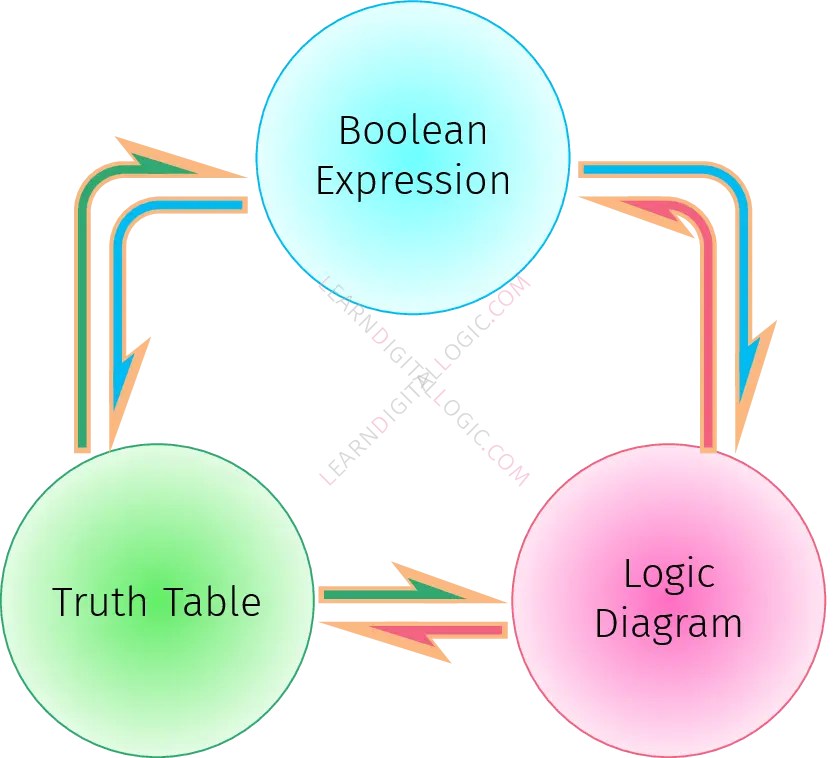
Core elements build the foundation of logic gate problems. By arranging different gates and connecting their inputs and outputs, we can create circuit diagrams that represent logical operations. Circuit designers express output functions through diagrams, Boolean expressions, or truth tables—three interchangeable representations of digital logic. This interconvertibility is illustrated in the figure below, which shows how each form can be translated into the others.
In this section, however, we will focus specifically on converting between logic diagrams and Boolean expressions, as well as calculating output values and estimating circuit latency. While truth tables are equally fundamental, converting them to other forms—especially Boolean expressions—is more labor-intensive without the tools of minterms and maxterms, which we will introduce in the next section. For now, our emphasis will remain on the structural and algebraic aspects of logic design.
Types of Basic Logic Gate Problems
- Logic Diagram to Boolean Expression: Given a circuit diagram, determine its corresponding mathematical representation.
- Logic Diagram to Output Value: Use the diagram to compute the output for a specific set of input values.
- Mathematical Notation to Logic Diagram: Interpret a Boolean equation and draw the equivalent logic circuit.
- Mathematical Notation to Output Value: Solve the Boolean equation using provided input values to find the output.
Each problem type strengthens different aspects of comprehension—from interpreting symbolic logic to visualizing circuitry.
Understanding Gate Latency
Beyond logical function, it’s important to recognize that gates are physical devices, built using transistors. Therefore, processing inputs takes time, and the delay before a gate produces a stable output is called its latency. As the exact physics may be complex, we can simplify the concept by assigning a fixed latency value to each gate.
Consequently, this leads us to another valuable category:
- Logic Diagram to Output Latency: Determine the total time a circuit takes to produce its final output, given the individual latencies of each gate in the diagram.
As circuits grow more complex, different gate types can have varied latencies, making these problems a great introduction to practical performance analysis.
In the upcoming sections, we’ll walk through detailed examples for each problem type. By breaking them down step-by-step, you’ll gain the confidence and clarity to tackle similar challenges on your own.
Ready to dive into the first category? Let’s decode diagrams into math!